CAD Drawn Versions Of Comet "Stick" Models
The models in this section of the web site are CAD drawn versions of Comet built up stick models. These models are tissue covered as opposed to the Comet series of Stuct-O-Speed all sheet models. The selection of models in this section are ones that were of personal interest and the plan packages represent a number of hours to produce. Examples will be added as time and personal interest permits. There were so many models developed by Comet during the time they were in business that it would take several life times to redraw all of them using CAD tools.
As is the case with other plans available from this web site, the plan packages are offered as Adobe PDF files.
WHEN PRINTING MAKE SURE THAT PRINT SCALING HAS BEEN TURNED OFF. That will help make sure each plan prints at the intended size.
There are several ways to transfer the part outlines to balsa. The one used personally is to print the parts directly on 1/32" balsa. A description of the method used to print the parts directly on balsa is provided here. Just click on the link. We then laminate the printed balsa sheets with a second sheet of 1/32" balsa (cross grain) to form parts that are 1/16" thick. That is the normal thickness of most of the parts in a Comet model design. If thicker wood is called out simply use the appropriate thickness of balsa to laminate with the printed 1/32" sheets.
An alternative method that works quite well is to print the parts on T-Shirt image transfer paper. That is paper used to create custom T-shirts with your own graphics. We have had very good results using the T-shirt transfer paper as a medium for transferring printed images to balsa. This eliminates the need for laminating sheets and also allows any printer to be used. The process for using iron on transfer paper is described here. Files containing mirrored images of the parts set up for printing on letter size transfer paper have been provided for each model to make it easier to use the iron-on transfer paper method of part transfer to balsa.
The plans presented here are probably better called "Based on Comet Designs". They retain nearly all of the features of the original designs but do include a few changes that reflect more current methods or what we feel are enhancements to the structural design resulting in better durability or ease of building.
If you have access to a 3D printer, you will find some 3D print files for propellers here. The 6" three blade prop is well suited for the P-51A and P-40C. The 7" two blade prop works well with the Stinson SR-7, and the 7 1/2" three blade prop is well suited for the Hellcat.

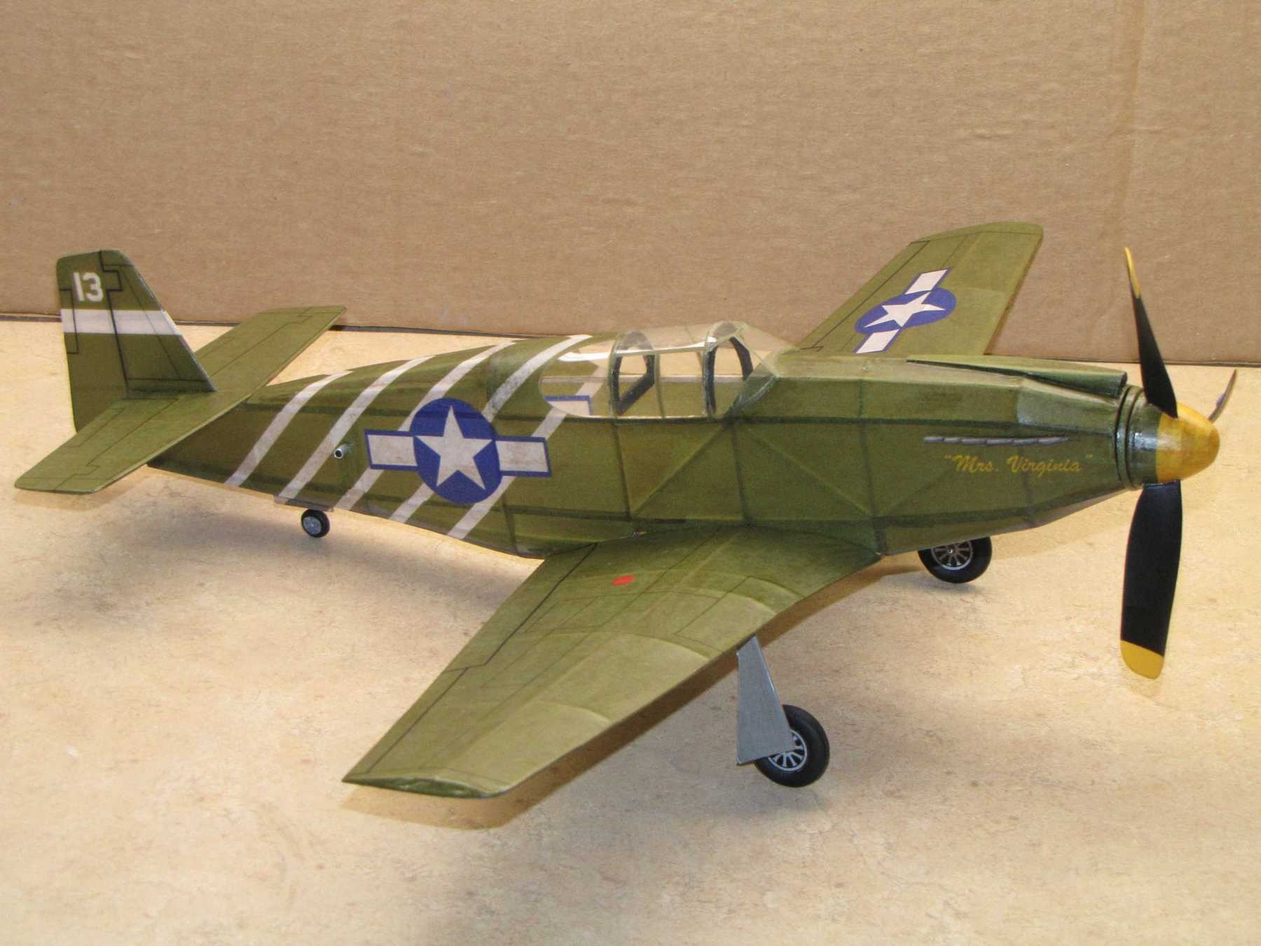
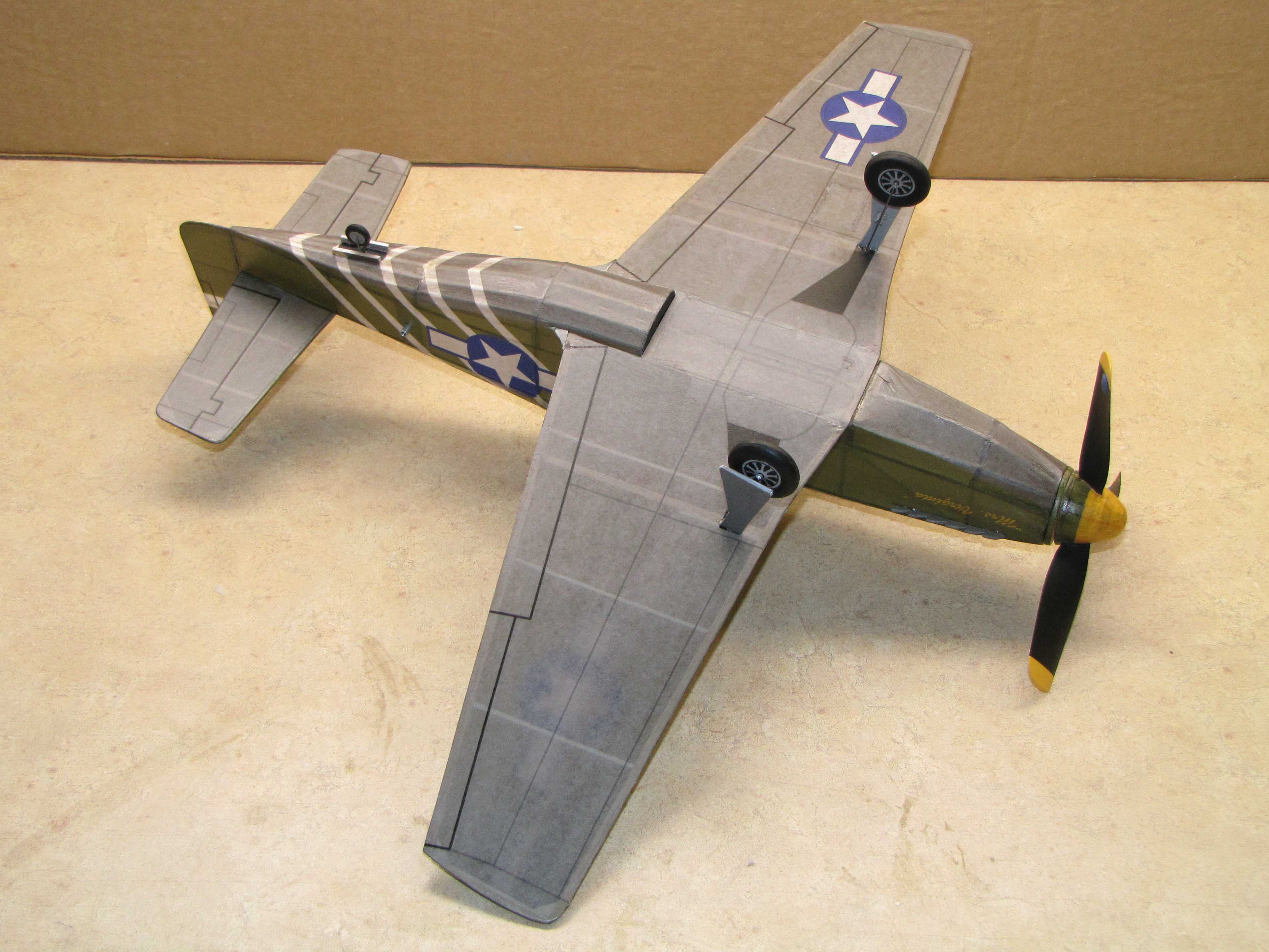
18" North American P-51A. One of the most prolific companies for developing varied model airplane designs and kits was Comet Models. They began designing and selling model airplane kits in the '30's and continued for much of that century before ceasing operations. During the life of the company they developed more designs than most people can catalog. We have always had a soft spot for the Comet "stick" models.
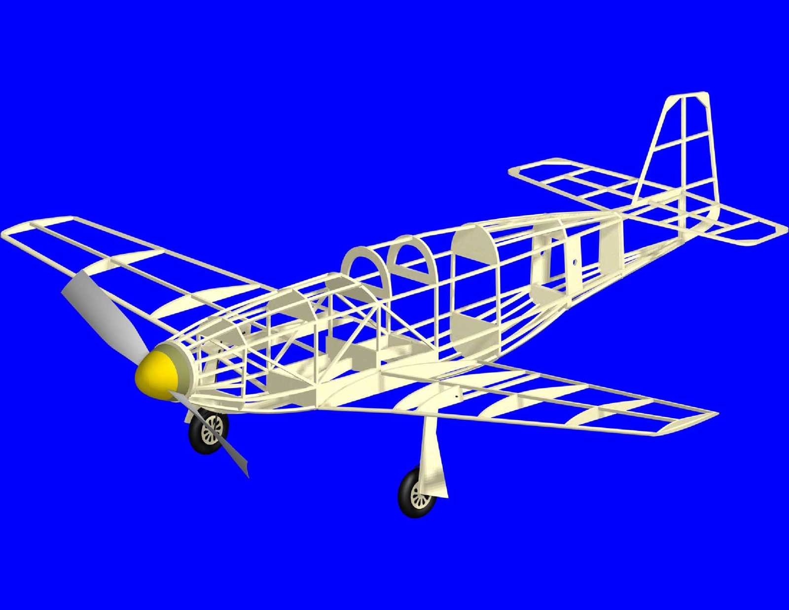
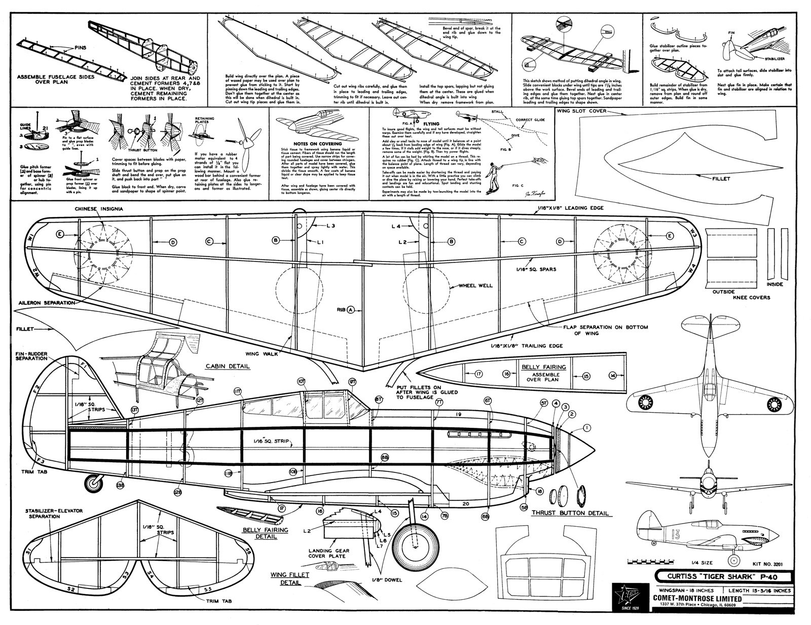
As a self teaching project for learning 3D CAD techniques it was decided to use one of the Comet designs as a platform. Many of the original plans and corresponding part drawings can be found on the Internet. We located one of our personal favorites, the 18" P-51A. That early model P-51 came after the North American Apache which was likely the actual airplane modeled by Comet. As presented, the Comet design has been tweaked just a bit so we are calling it a P-51A.
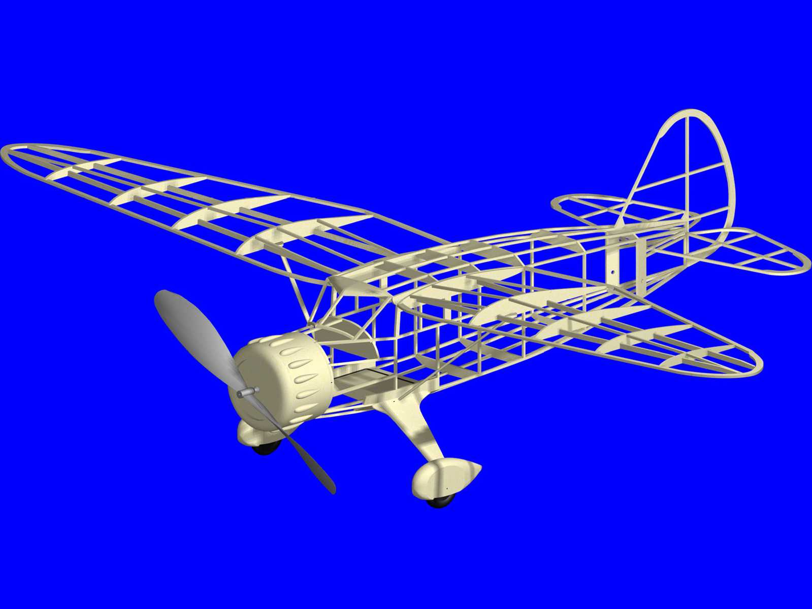
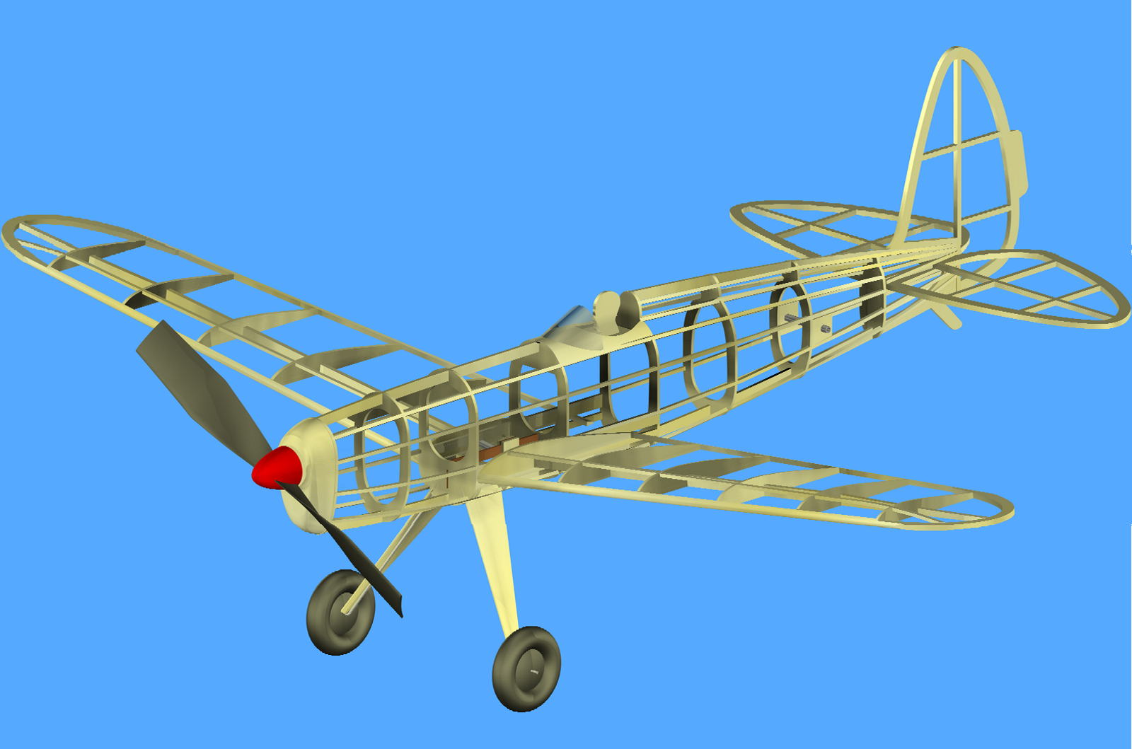
The images show a CAD 3D rendering of the model based on the developed plan, and the actual model built from the plan. The model is covered with tissue that has the color and markings applied with an ink jet printer. The tissue has two coats of nitrate clear dope that had been thinned with equal parts of thinner. The three bladed prop was made from two conventional plastic rubber props.
A few minor changes have been made to the structural design. These are quite minor. Examples include addition of a fuselage former to make it easier to form the transition between the bottom air scoop and the rear fuselage, use of balsa plates where the wing attaches to the fuselage, and the landing gear arrangement. The nose former has also been adjusted to allow for a removable nose plug for stretch winding the motor. The CAD drawn plan package is provided below. Parts laid out for printing on letter size sheets of T-shirt transfer paper are also provided below. The original plan and part set is provided below. The tissue layouts used for creating the printed tissue on this model have been provided below. The method used for making the three bladed prop can be found here.
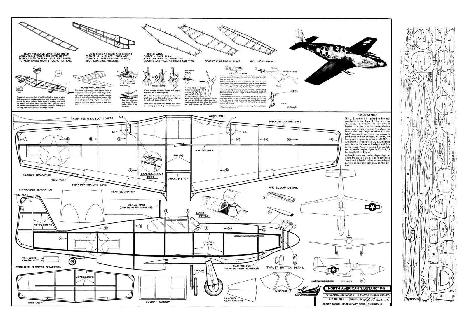
There were two versions. One used a built up box fuselage with formers added. The other used the crutch and former method of fuselage construction. The package being offered is the box based fuselage design.
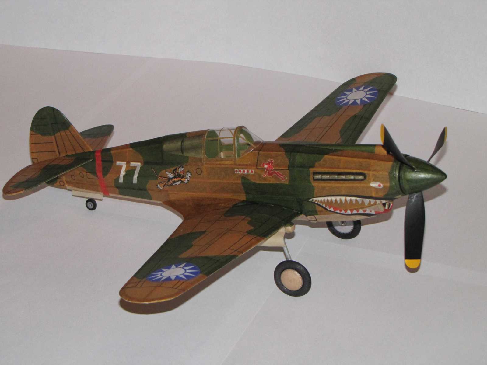
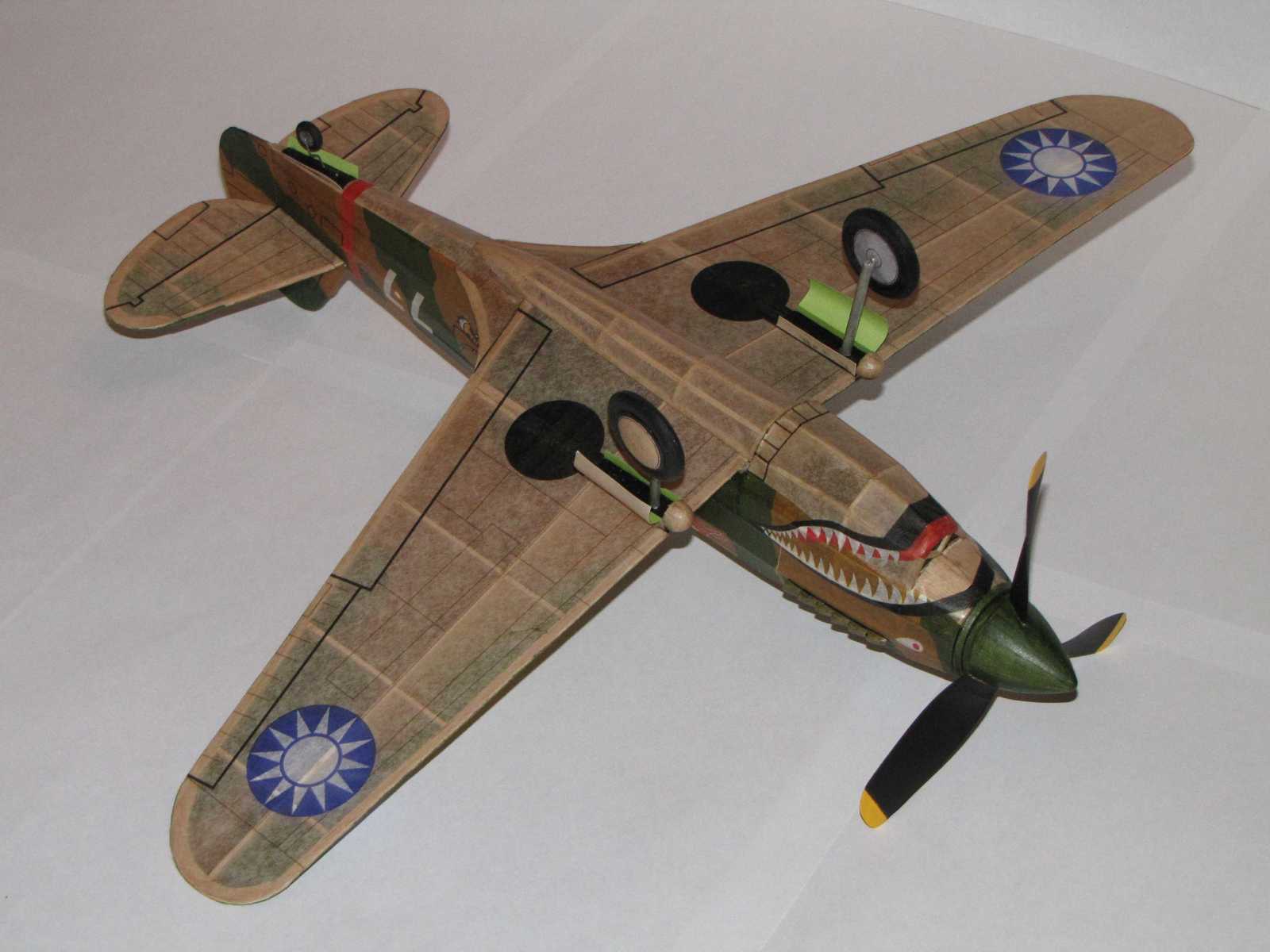
The images show a CAD 3D rendering of the model based on the developed plan, and the actual model built from the plan. The model is covered with tissue that has the color and markings applied with an ink jet printer. The tissue has two coats of nitrate clear dope that had been thinned with equal parts of thinner. The three bladed prop was made from two conventional plastic rubber props.
A few minor changes have been made to the structural design. The 1/16" square top mounted wing spar has been replaced with a full depth 1/16" sheet balsa spar. A few diagonals have been added to the fuselage to improve torsional rigidity. The landing gear installation uses piano wire rather than dowels and pins. The nose side profile has been adjusted to be in better conformance to the full scale airplane profile. The nose former has also been adjusted to allow for a removable nose plug for stretch winding the motor. The CAD drawn plan package is provided along a package for the parts laid out for printing on letter size sheets of T-shirt transfer paper. The original plan and part set is also provided. The tissue layouts used for creating the printed tissue on this model are included. The method used for making the three bladed prop can be found here.
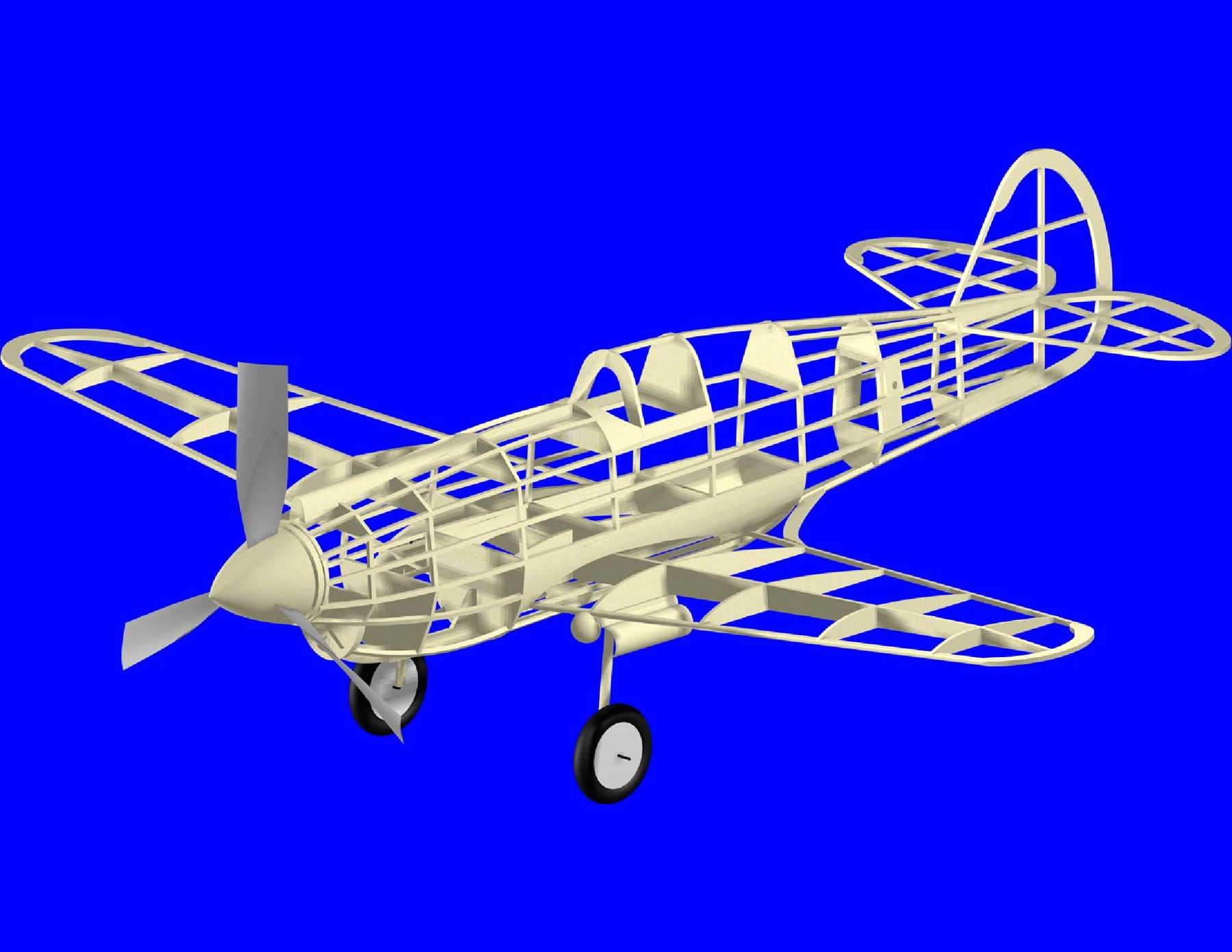
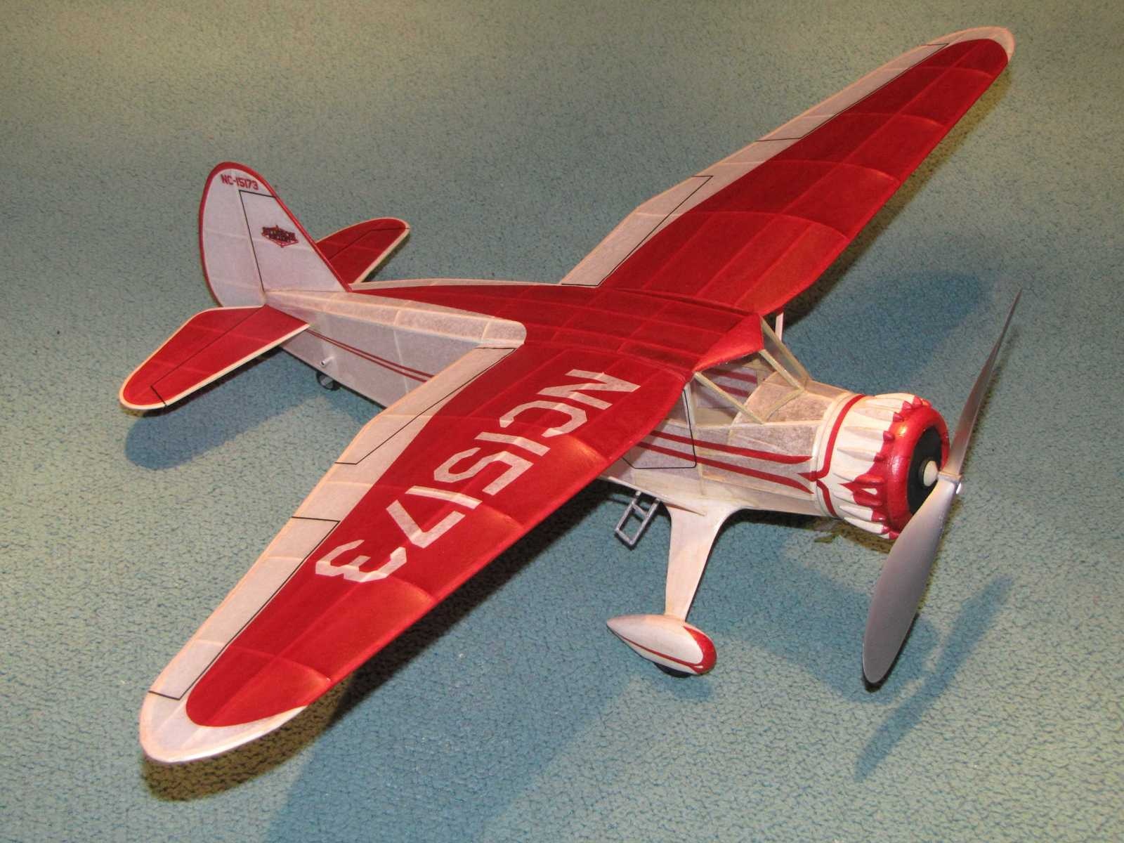
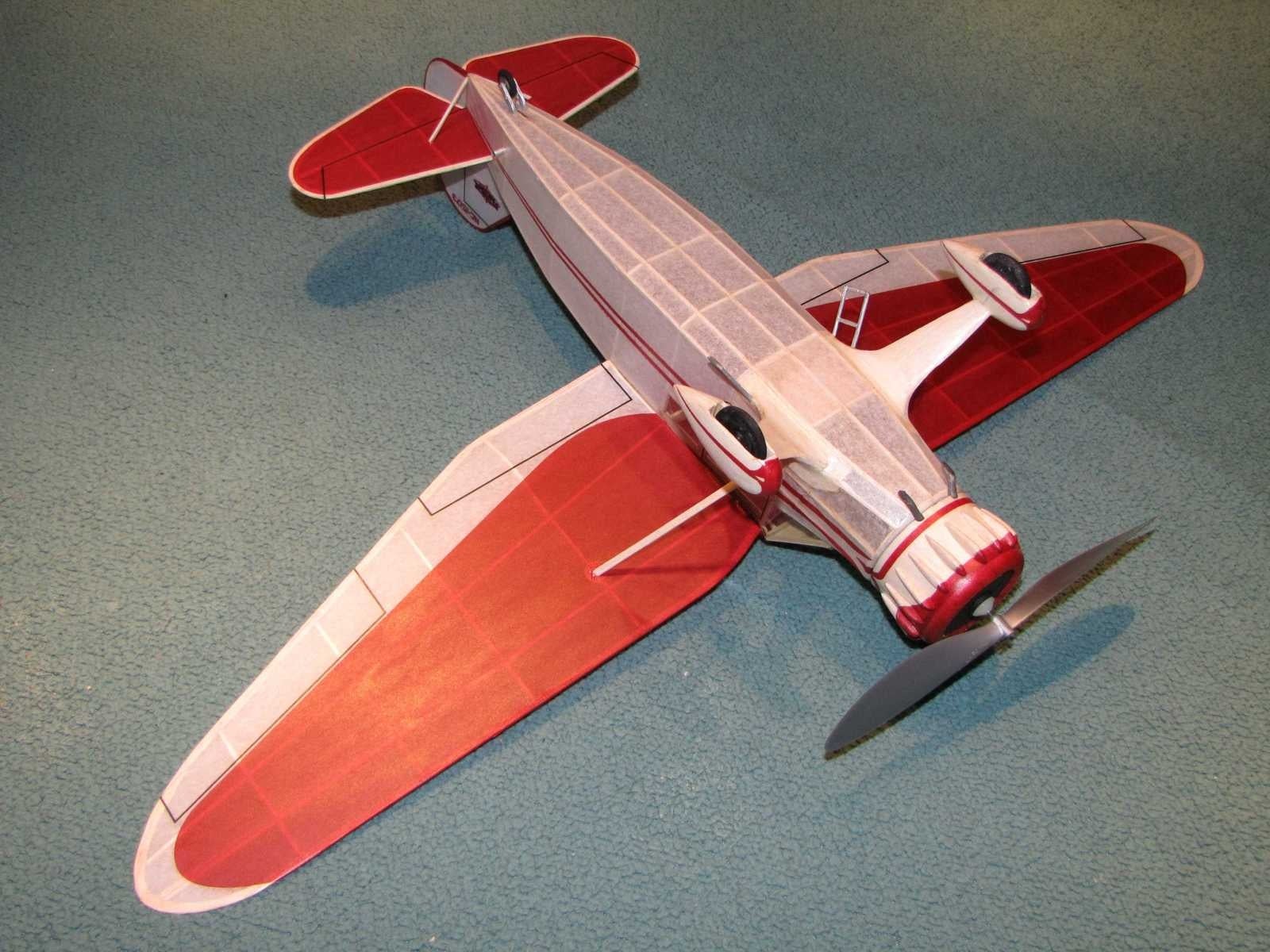
The images show a CAD 3D rendering of the model based on the developed plan, and the actual model built from the plan. The model is covered with tissue that has the color and markings applied with an ink jet printer. The tissue has two coats of nitrate clear dope that had been thinned with equal parts of thinner.
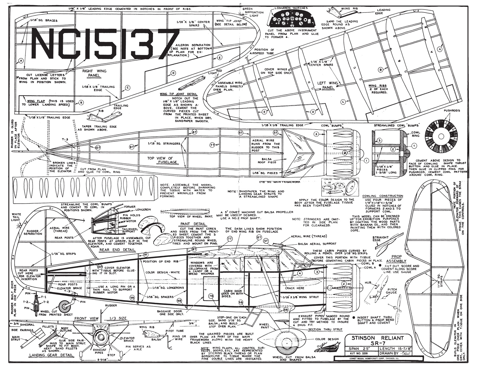
As was done with the P-51A and P-40C, a few structural modifications were incorporated in the plan for the Stinson. These included addition of a top 1/16" square wing spar, addition of piano wire to the landing gear installation, addition of balsa sheet filler to the landing gear mount area, use of balsa for the cowl rather than paper, and a removable nose plug to allow stretch winding. One other change made was the license number shown on the original kit plan. A look up of that number shows it was actually issued to a Monocoupe. Reversing the last two digits corresponded to a Stinson SR-7. Photos were found of the actual airplane and the markings were taken from those photos for the model.
The CAD drawn plan package is provided along with the parts laid out for printing on letter size sheets of T-shirt transfer paper. The original plan and part set is here is provided for reference. The tissue layouts used for creating the printed tissue on this model are also provided.
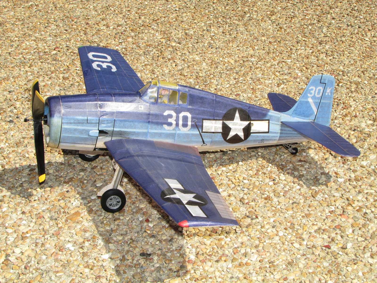
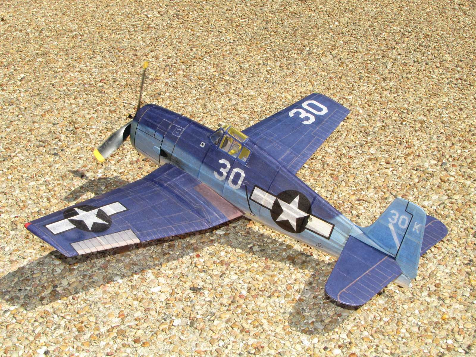
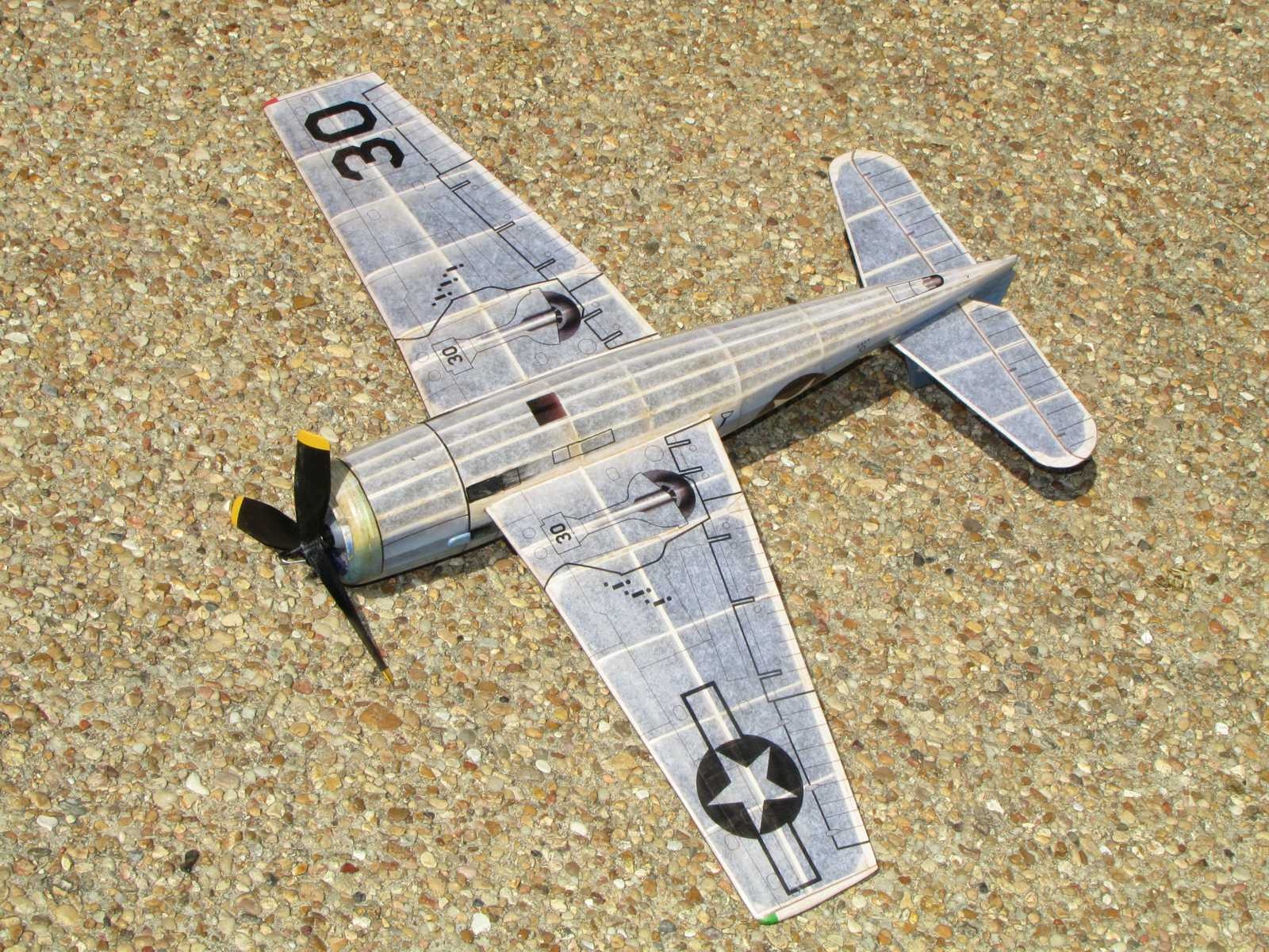
The model is covered with tissue that has the color and markings applied with an ink jet printer. The tissue has three coats of nitrate clear dope that had been thinned with equal parts of thinner. The propeller, wheels, and removable nose plug were created with a 3D printer.
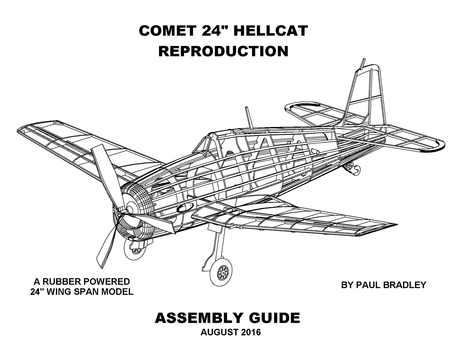
A few modifications were incorporated in the CAD drawn plan for the Hellcat. Examples are addition of top 1/16" square wing sub-spars, making the landing gear removable, addition of balsa block filler below the fin, a removable nose plug to allow stretch winding, and a few other minor changes. Markings are for a Hellcat that served in VF-1 on the USS Yorktown in the Marianas June 1944 (source: U.S. Navy Carrier Fighters Of World War II, Squadron/Signal Publications).
Available for download is an illustrated assembly guide, plan package that prints on US legal paper (8.5"x14"), tissue printing layouts with the unit markings used for the model in the photos, tissue layouts without any unit markings, parts normal orientation, parts mirrored for iron on transfer paper, the 3D printer file for the propeller, the 3D printer file for the wheels, and the 3D printer file for the removable nose block set up for a Gizmo Geezer front end.
Note that the 3D printed 7.5" diameter propeller used for the model that is provided here has a hypotwist pitch distribution. The pitch to diameter (P/D) ratio from the hub out to the 75% radius point is 1.2. From the 75% radius point out to the tip the P/D increases linearly to 1.8. The use of hypotwist is based on a paper by Bruce Holbrook that is available on the National Free Flight Society web site in the Technical Library section.
A set of laser cut parts for this model can be purchased from Aerowerkes.com. The parts package is in the SRK section under COM 3505PB.


Files to Download
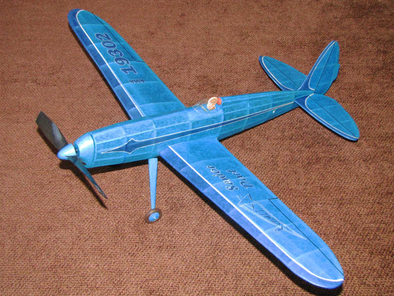
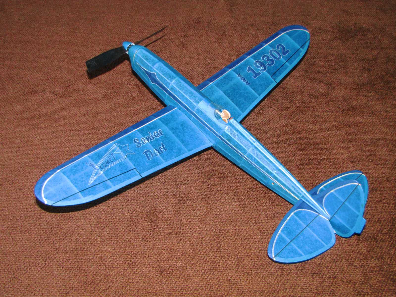
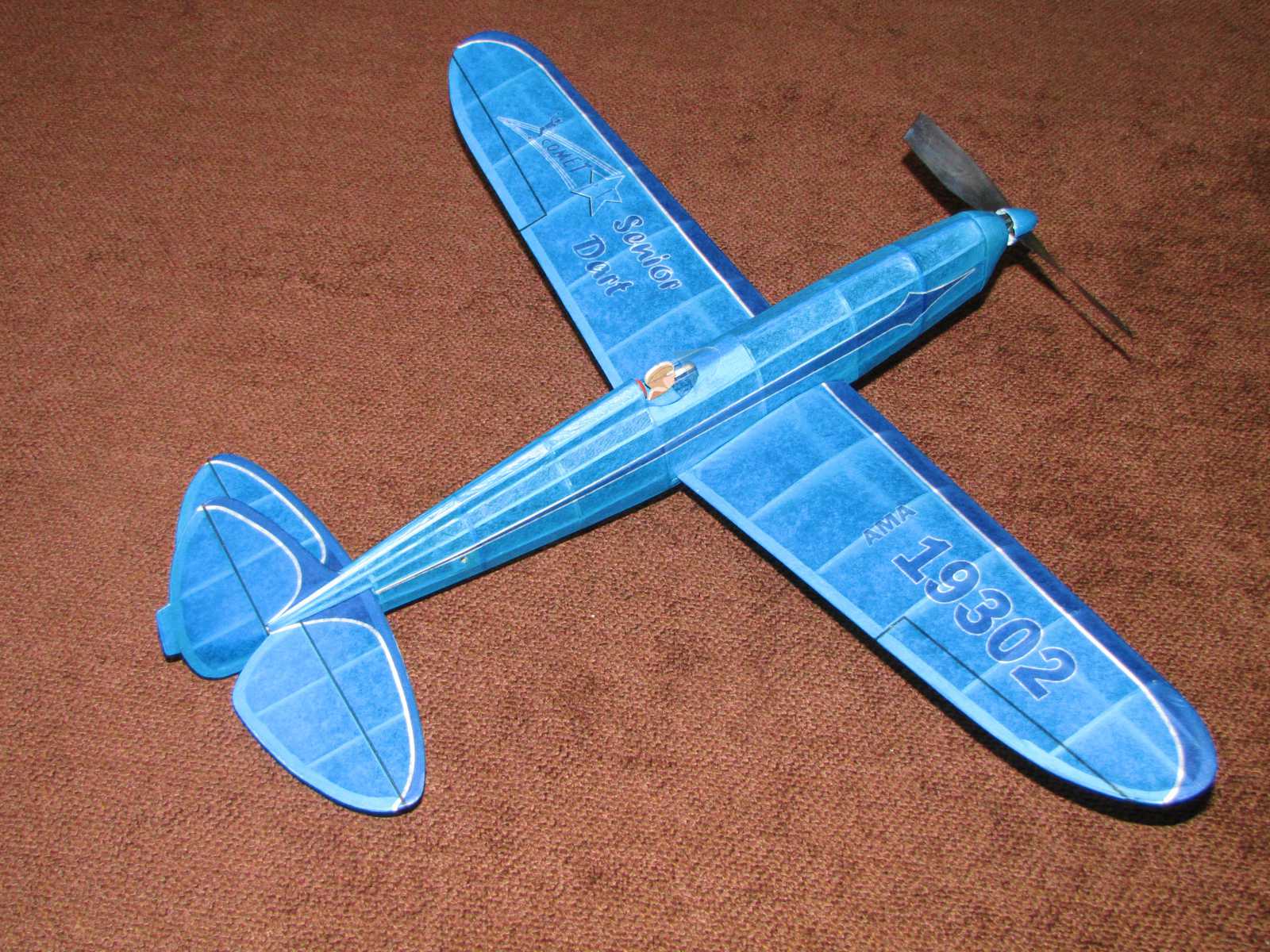
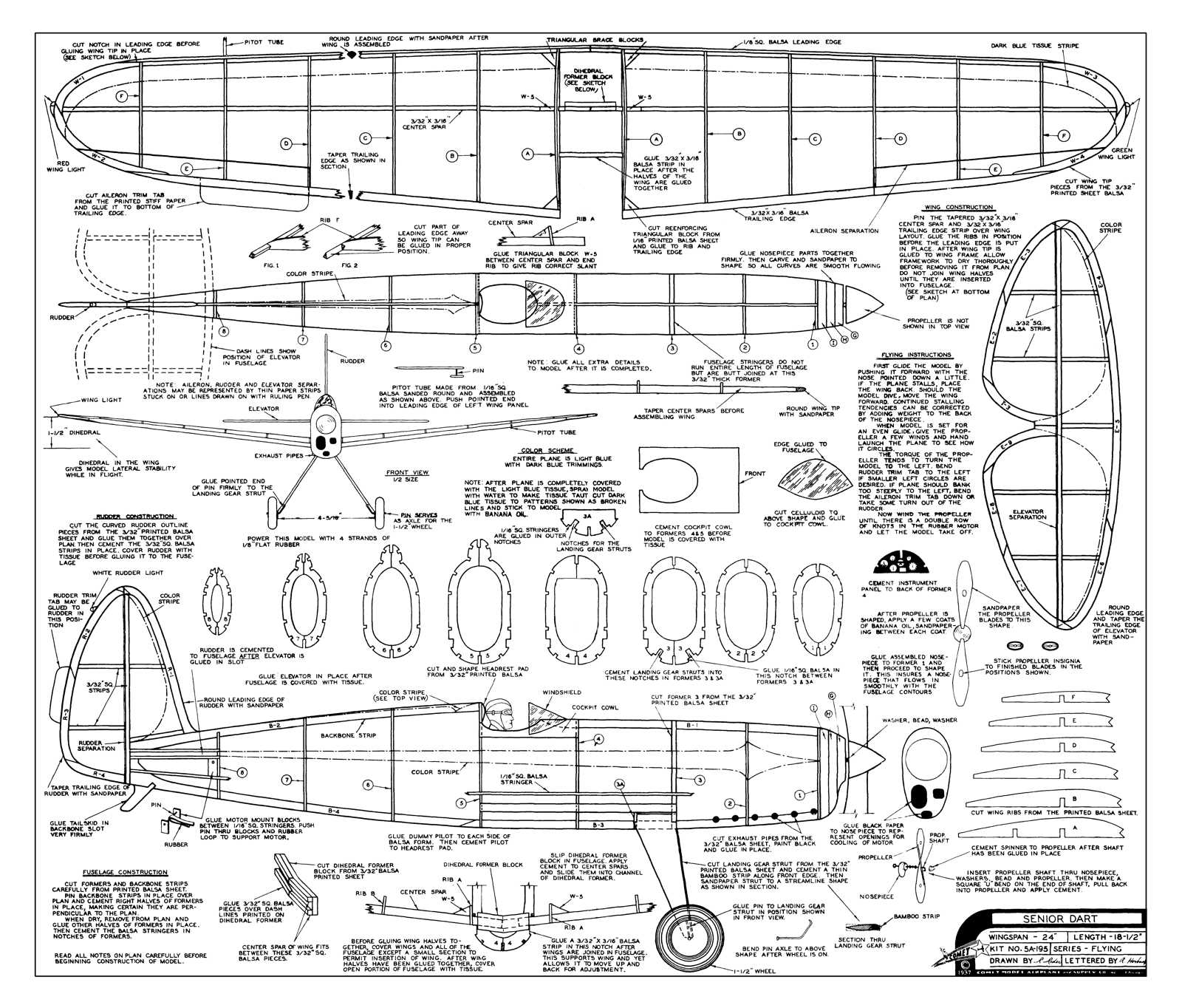
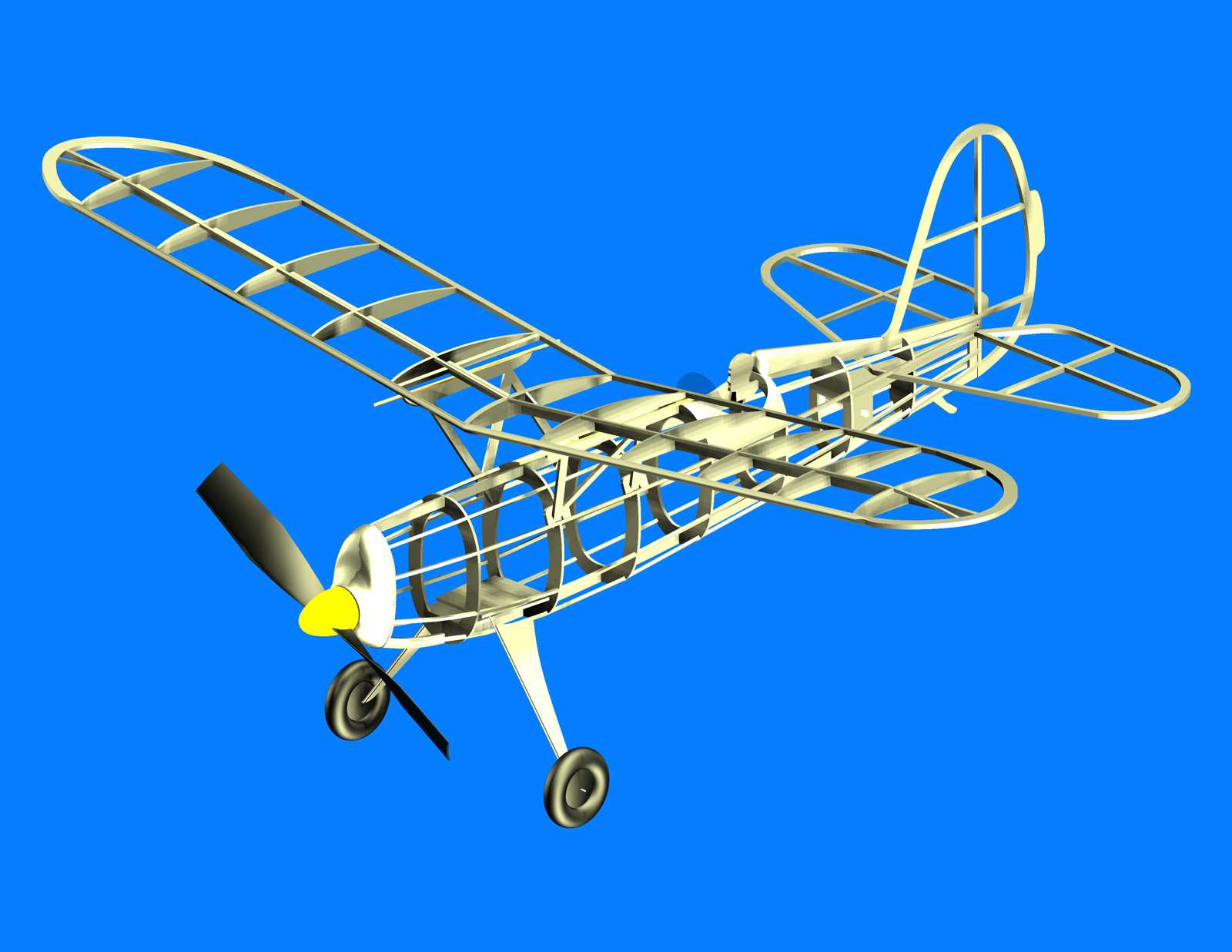
This is the Comet Senior Dart. The model has a 24" wing span. It is covered with ink jet printed tissue. The original kit plan has a copyright date of 1937. A unique feature of this design is a wing that can be moved forward or back to achieve the best Center of Gravity (CG) location.
The drawing package presented here is a CAD re-draw of the original kit plan. The CAD drawing was developed to help make sure all of the parts would fit correctly and to incorporate a few structural design changes to reflect current day building practices. The most notable change made to the original kit plan is the way the wing is mounted in the fuselage. The ability to move the wing forward and back has been retained, but the wing panels have also been set up to be removable. The wing panels have aluminum tubes integrated with the root ends of the main wing spars that slide into corresponding short aluminum tubes in a sliding wing joiner. The wing panels are retained with magnets located in the end of each wing tube.
The original kit plan calls for 1 1/2" wheels. This is a fairly large size for a model with a 24" wing span. The example in the photos is using 1" diameter wheels. This reduces the overall weight of the model and the drag during flight. The plan drawing retains the original 1 1/2" wheels. The wheels used on the model built from this plan package were created with a 3D printer. The 3D model file for the wheels is provided should you have access to a 3D printer.
As an experiment, a 3D printed nose block was also created for a weight comparison to the laminated balsa nose block shown on the plan. The laminated balsa nose block ended up weighing 2.1 grams. The 3D printed nose block weighs 3.4 grams. The 3D model file for the 3D printed nose block is provide here should you have access to a 3D printer and would like to use the slightly heavier nose block. If you do create a 3D printed nose block from the supplied file, it is printed in two parts. Print using supports. After printing remove the supports from the main part of the nose block. The two printed parts are then glued together to form a hollow nose block. If possible, use ABS when printing the two parts. ABS can be securely glued together with acetone. It can also be easily sanded to create a clean post print outer surface.
Provided here are the plan package (585 kb), and assembly guide (1.36 mb), covering layouts for the model shown in the photos (723 kb), the parts laid out for iron on transfer paper (86.2 kb), a 3D print file for the spinner (3.35 mb), a 3D print file for the wheels (1.95 mb), a 3D print file for the nose block (33.6 mb), and a PDF copy of the original kit plan (921 kb). The model in the photos is using a 7" diameter 3D printed prop from the 3D printed propeller section of this web site.

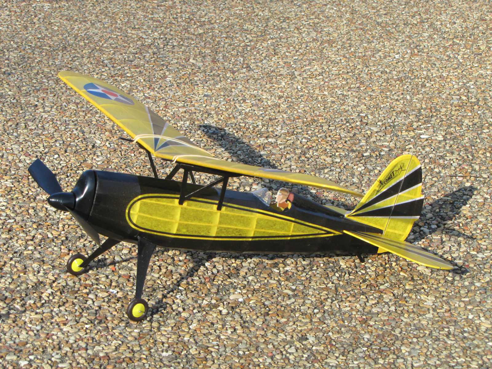
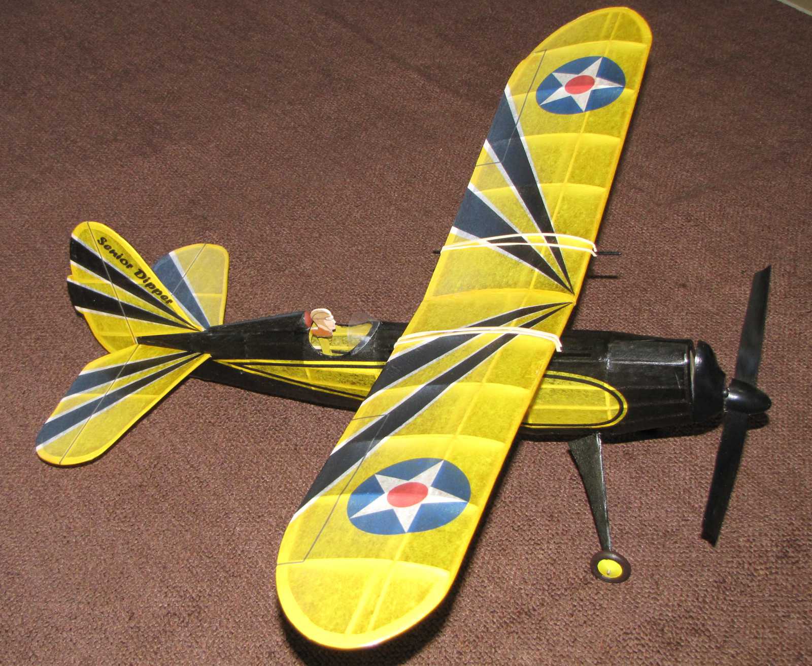
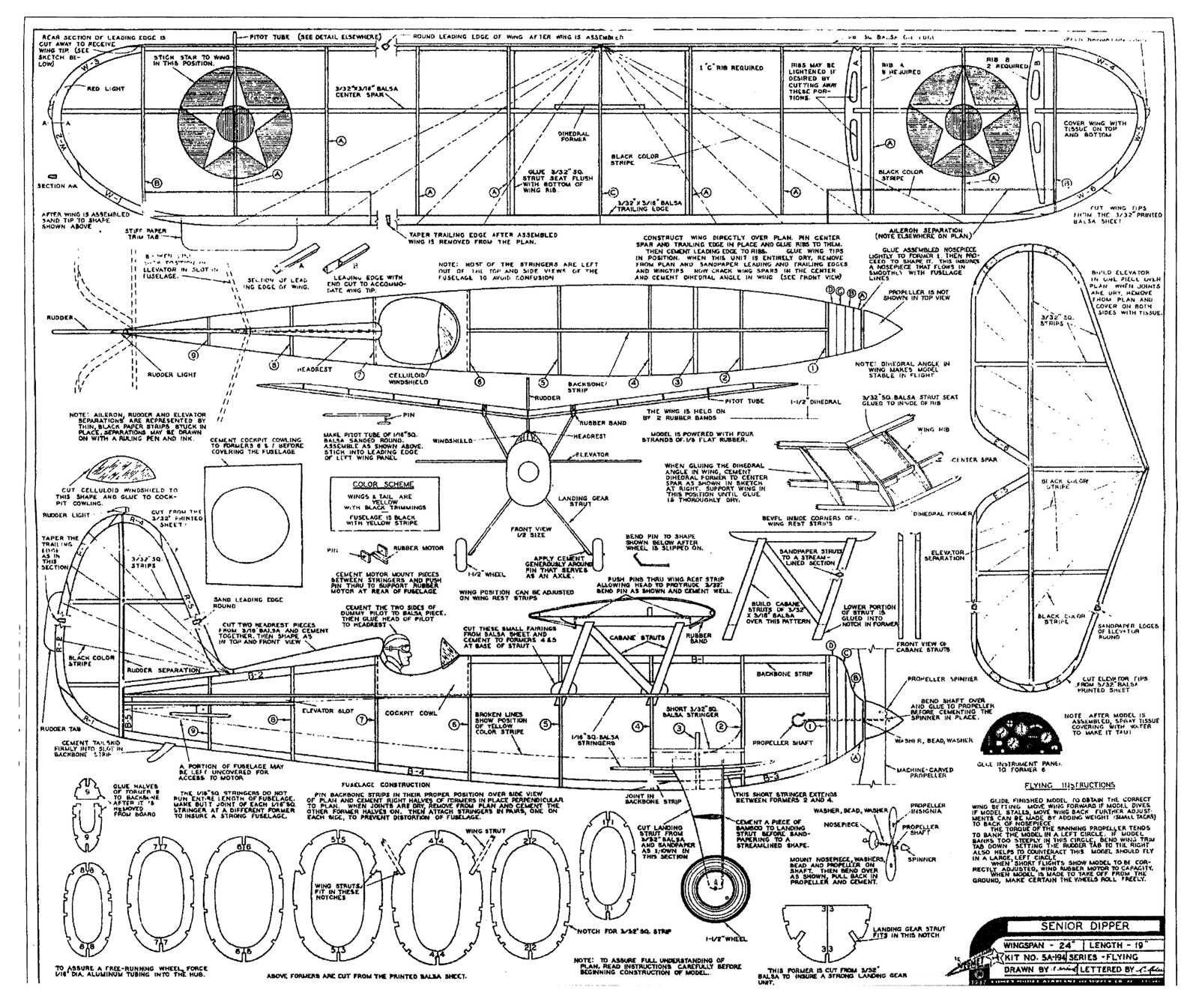
This is the Comet Senior Dipper. The model has a 24" wing span. It is covered with ink jet printed tissue. The original kit plan has a copyright date of 1937.
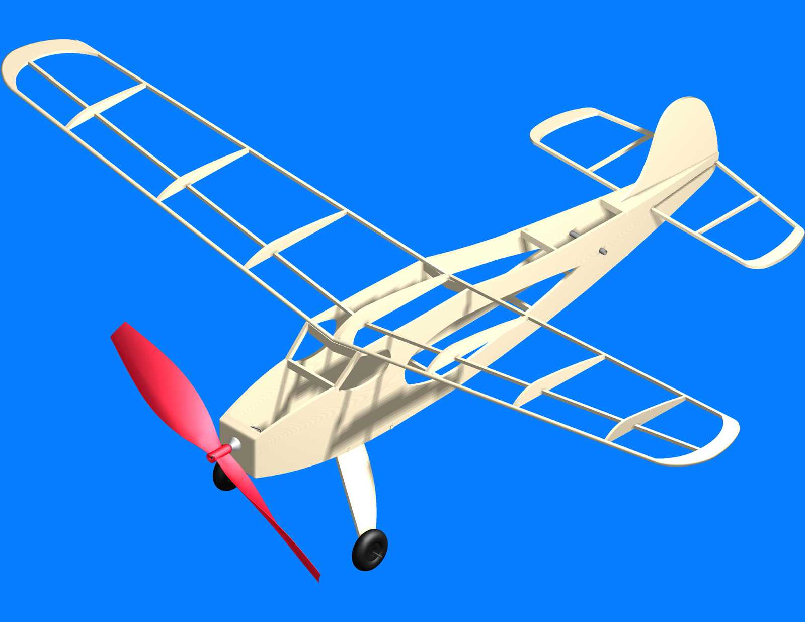
The drawing package presented here is a CAD re-draw of the original kit plan. The CAD drawing was developed to help make sure all of the parts would fit correctly and to incorporate a few structural design changes to reflect current day building practices.
The original kit plan calls for 1 1/2" wheels. This is a fairly large size for a model with a 24" wing span. The example in the photos is using 1" diameter wheels. This reduces the overall weight of the model and the drag during flight. The plan drawing retains the original 1 1/2" wheels. The wheels used on the model built from this plan package were created with a 3D printer. The 3D model file for the wheels is provided should you have access to a 3D printer.
A 3D printed nose block was also created for a weight comparison to the laminated balsa nose block shown on the plan. The laminated balsa nose block ended up weighing 2.4 grams. The 3D printed nose block weighs 4 grams. The 3D model file for the 3D printed nose block is provide here should you have access to a 3D printer and would like to use the slightly heavier nose block. If you do create a 3D printed nose block from the supplied file, it is printed in two parts. Print using supports. After printing remove the supports from the main part of the nose block. The two printed parts are then glued together to form a hollow nose block. If possible, use ABS when printing the two parts. ABS can be securely glued together with acetone. It can also be easily sanded to create a clean post print outer surface.
Provided here are the plan package (730 kb), and assembly guide (1.51 mb), covering layouts for the model shown in the photos (47.9 kb), the parts laid out for iron on transfer paper (141 kb), a 3D print file for the spinner (8.45 mb), a 3D print file for the wheels (21.4 mb), a 3D print file for the nose block (38.8 mb), and a PDF copy of the original kit plan (1.61 kb). The model in the photos is using a 7" diameter 3D printed prop from the 3D printed propeller section of this web site.


This is the Comet Meteor. The Meteor is a sport rubber powered model that was introduced in the 70's. This was the last new kit offering before the company ceased operations. The structure is more robust that would be typical of a model this size intended for duration competitions. That said, it is capable of very satisfying flights. The robust structure can help prevent fly aways when the model encounters light to medium strength thermals. Strong thermals could result in a lost model. Use light wood but contest weight wood is not required.
Provided are the plan (34" x 22"), printed tissue layouts for the box art graphics, and a CAD file for laser cutting the parts. The cut file is provide for personal use and is not authorized for commercial use without permission. The cut lines have been adjusted for a laser kerf value of .005".
If you do not have access to a laser cutter or don't enjoy cutting parts out of a balsa sheet, a laser cut kit for this model is now available from BMJR Model Products.


This is the Comet Sparrow. It dates back to 1947. It has simple construction and is intended for sport flying. It was a low cost kit with a minimum of structure and materials. This reproduction retains most of the original design but does incorporate a few changes to make it easier to handle and build. The most notable change is the landing gear. Piano wire legs have been added along with a bottom plate for attaching the landing gear legs. The nose block has been increased in thickness to give it more strength.
Provided are the plan (22" x 17") and a reorganized copy of the plan that can be printed on U.S. standard letter size sheets (11" x 8.5").

In the 1940's Comet developed a kit line intended to encourage young people to develop an interest in aviation and model aviation called the Air Youth of America series. They designed five kits ranging in build difficulty from a simple all sheet balsa glider to a full fuselage built up stick and tissue outdoor model capable of fly away performance.
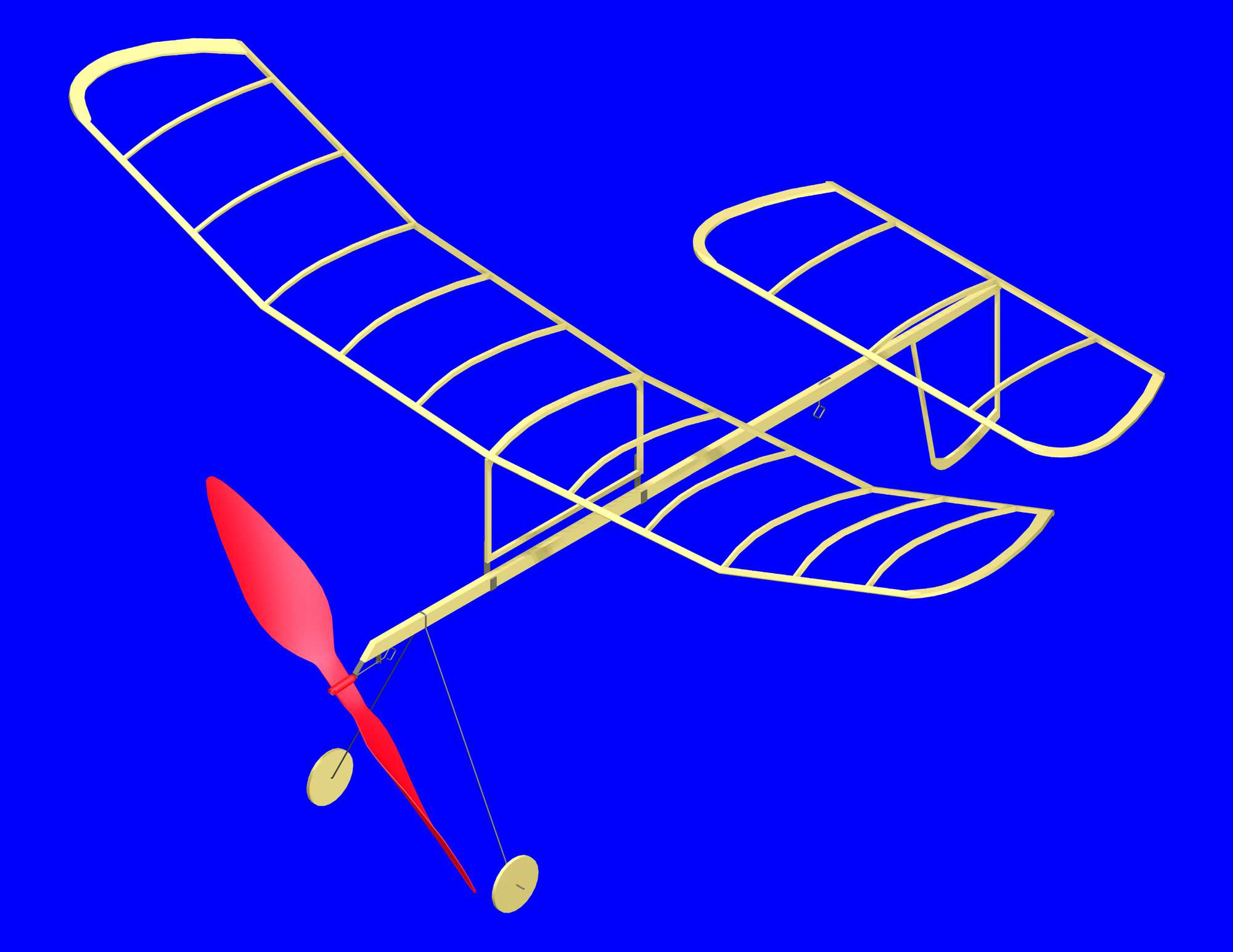
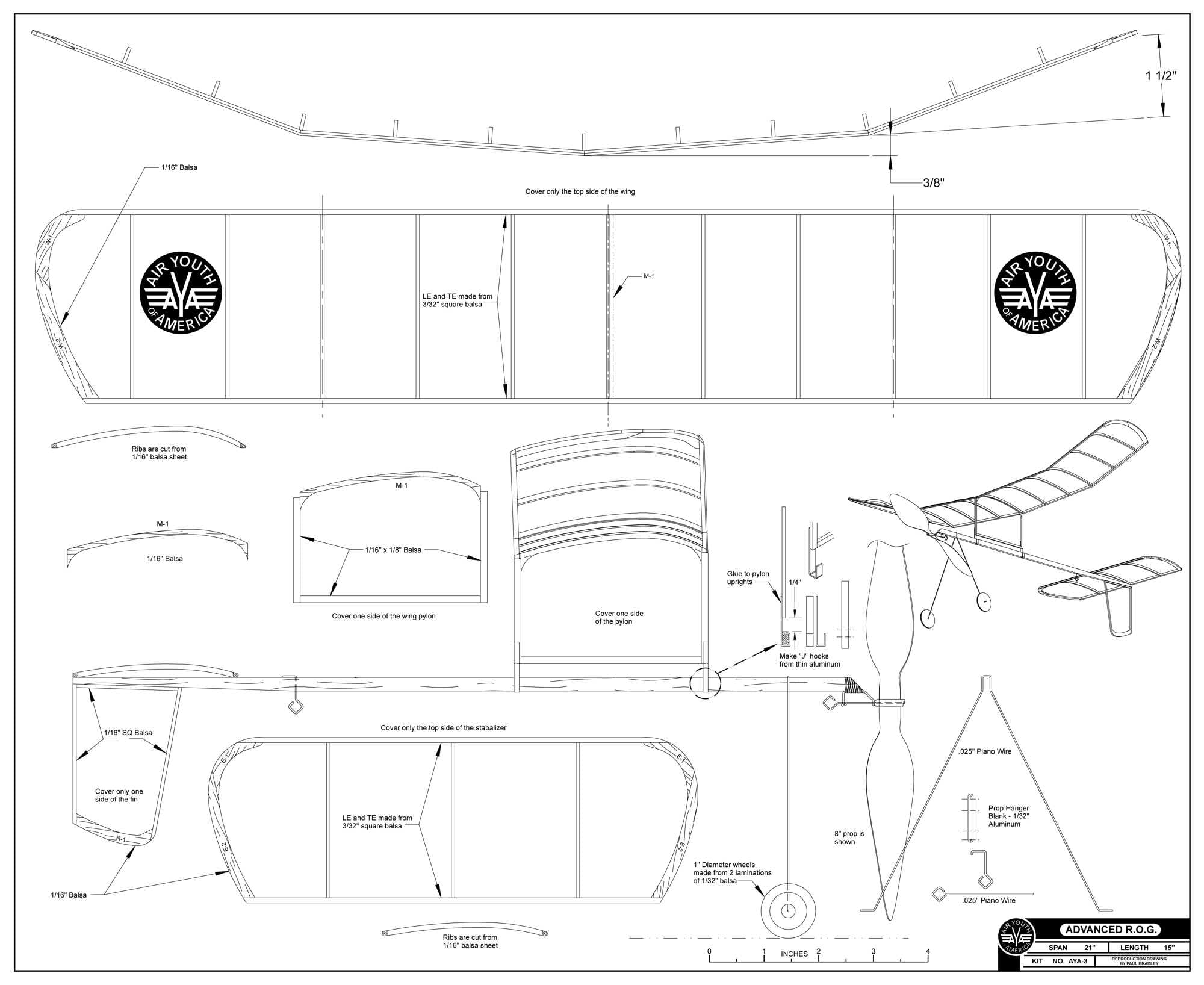
The third kit in the series was the Advanced R.O.G. (Rise Off Ground). ROG style models were popular at the time for flying indoors. The beginner level model typically had flat flying surfaces made from 1/16" square balsa sticks. This "advanced" ROG incorporates a wing and stabilizer profile that is cambered (has an airfoil). Adding camber to the flying surfaces introduced a slight increase in build difficulty both in structural assembly and covering. This kit laid the foundation for the next kit in the series that used a built up fuselage and flying surfaces that not only had camber, but were also covered on both sides. The example in the photo was built by John Pakiz, a long time model airplane builder who resides in Omaha, Nebraska.
The Comet Advanced R.O.G. has nice performance and represents a very satisfying sport indoor model. The provided plan is a re-draw of the original that retains all of the elements of the original design. The only deviations from the original plan is a suggested plastic propeller, and a pig tail style prop hanger to allow easy propeller changes.
Provided is the 18" x 22" plan and a 3D printable stl file for a 8" diameter Larrabee blade profile propeller suitable for this model.